Artefact Illustrations
Drawing Artefacts
In Semester 2, Week 6 2021, Karin Sowada gave a tutorial lesson to AHIS3306 on how to create accurate artefact illustrations according professional standards. The required equipment for the artefact illustration tutorial:
- A4 1mm graph paper (printed to actual size)
- Object from home (I chose a bottle opener)
- Pencil
- Sharpener
- Mechanical pencil
- Eraser
- Ruler
- Divider
- Several small set squares (with mm going to the edge)
- Blutak or Sticky tape
What I used...
Unfortunately due to Covid-19 lock-down I didn't have all the required equipment. The equipment I used:
- A4 1mm graph paper - printed to scale
- A bottle opener - for the object used
- A mechanical pencil with attached eraser
- A ruler
- Sticky tape to hold the object in place
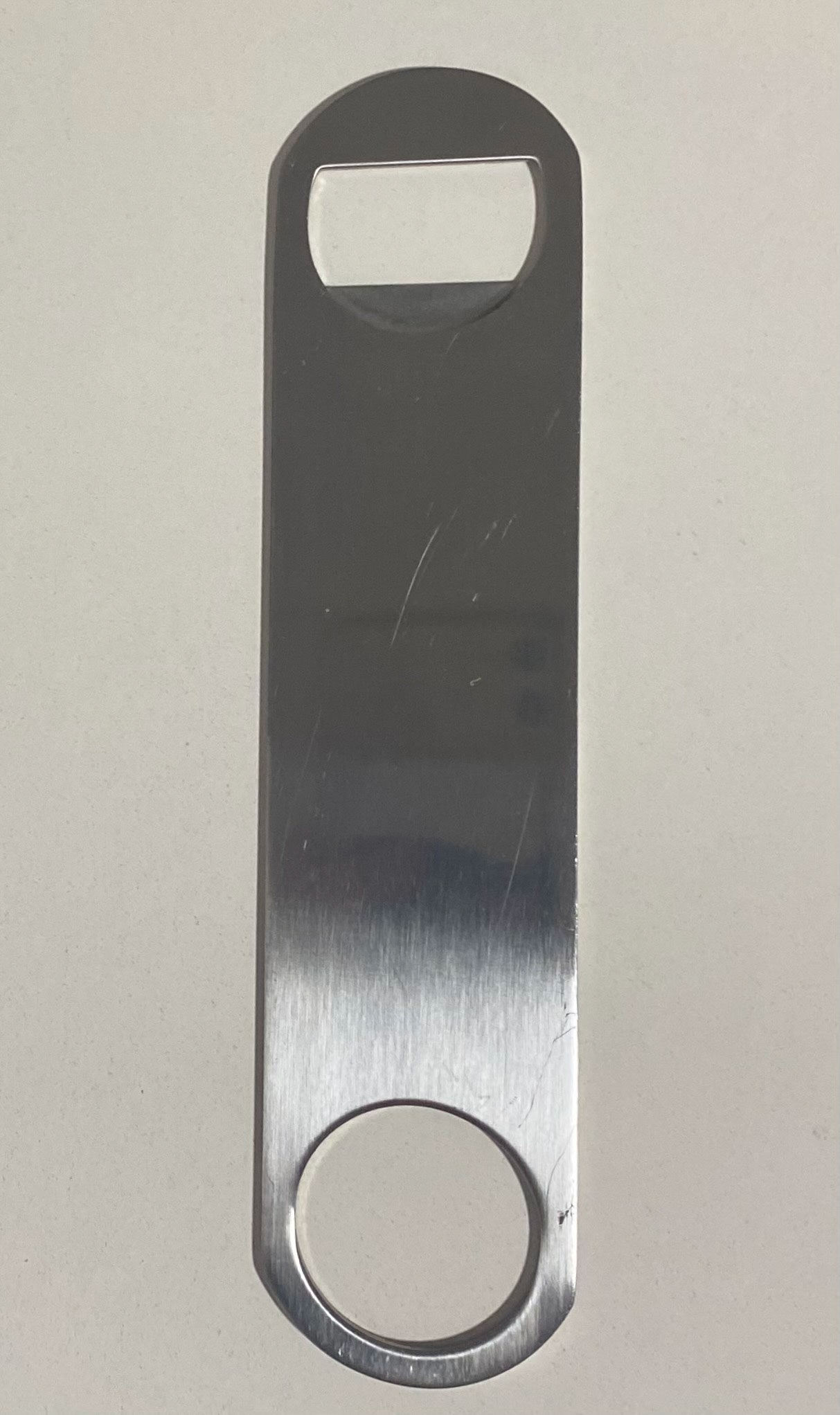
Illustration of original object
Step-by-step process
- Firstly, I downloaded the A4 1mm graph paper provided by Karin Sowada on ilearn.
- Choosing the object to draw was the next step. Karin explain that a flat object would be simpler to illustrate for this exercise. I looked around the kitchen and decided to draw a bottle opener as it is flat and quite simplistic for a beginner.
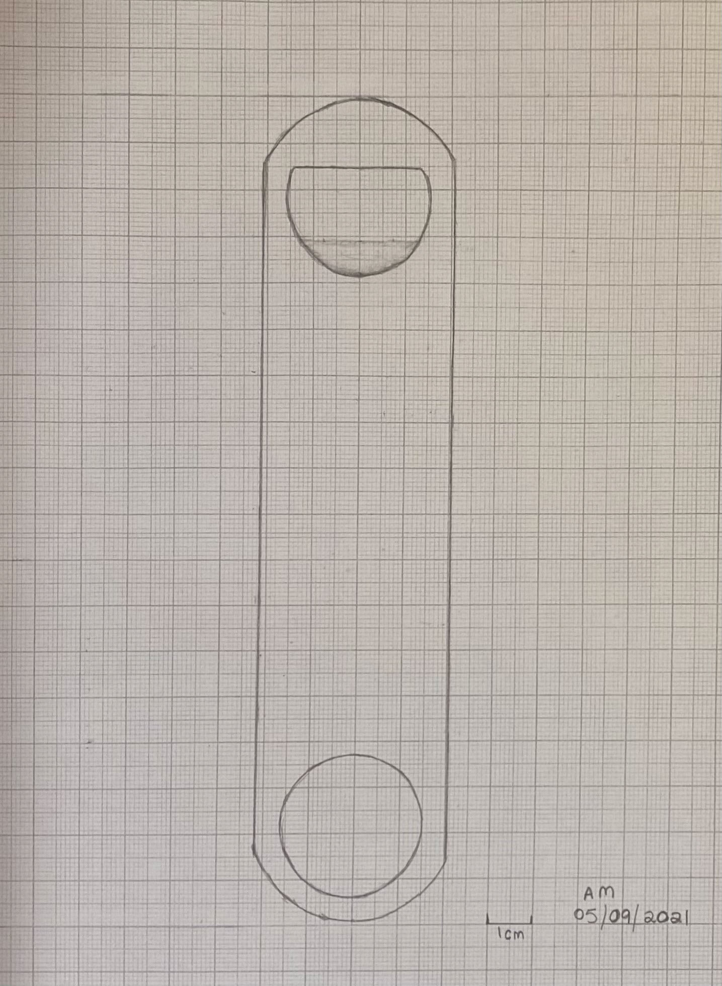
- Setting up the area - With the graph paper in front of me, I positioned the object in the middle. Taking note of the length I marked the scale with a ruler in which it will be drawn in between. Using the sticky tape, I positioned the object between the two points and attached the tape to the underside of the object to ensure stabilisation.
- Outline - Now I have my object positioned correctly on my paper, I used the ruler as a guide to assist with the outlining process. Each centimeter along the exterior of the object I would place a mark with the pencil for further guide when joining.
- Joining the outline - Once the marking of the outline was finished, I took away the object from the paper and meticulously joined each mark using the ruler as a guide for the appropriate straight lines needed. In relation to the curved end of the object symmetry is key.
- At the top of the object there is a half circle. The bottom of that half circle is a depression of the material shown by the light shading. To formulate the sizing of the depression I measured the flat surface of the interior circle. This measured at 2.5cm. At 5mm from the edge on either side, the bottom of the circle measured exactly 5mm. I placed a mark for this outline on either side. I then marked the middle of the 2.5cm and measured along the object to discover the width of the depression is 7mm. Once the illustration was completed I used some shading to describe the depression on the surface, and erased the scale lines the object was drawn in between.
- Lastly, I put a 1cm scale at the bottom of the image, wrote my initials and dated the illustration.
Adobe Illustrator - Artefact Illustration Digitisation
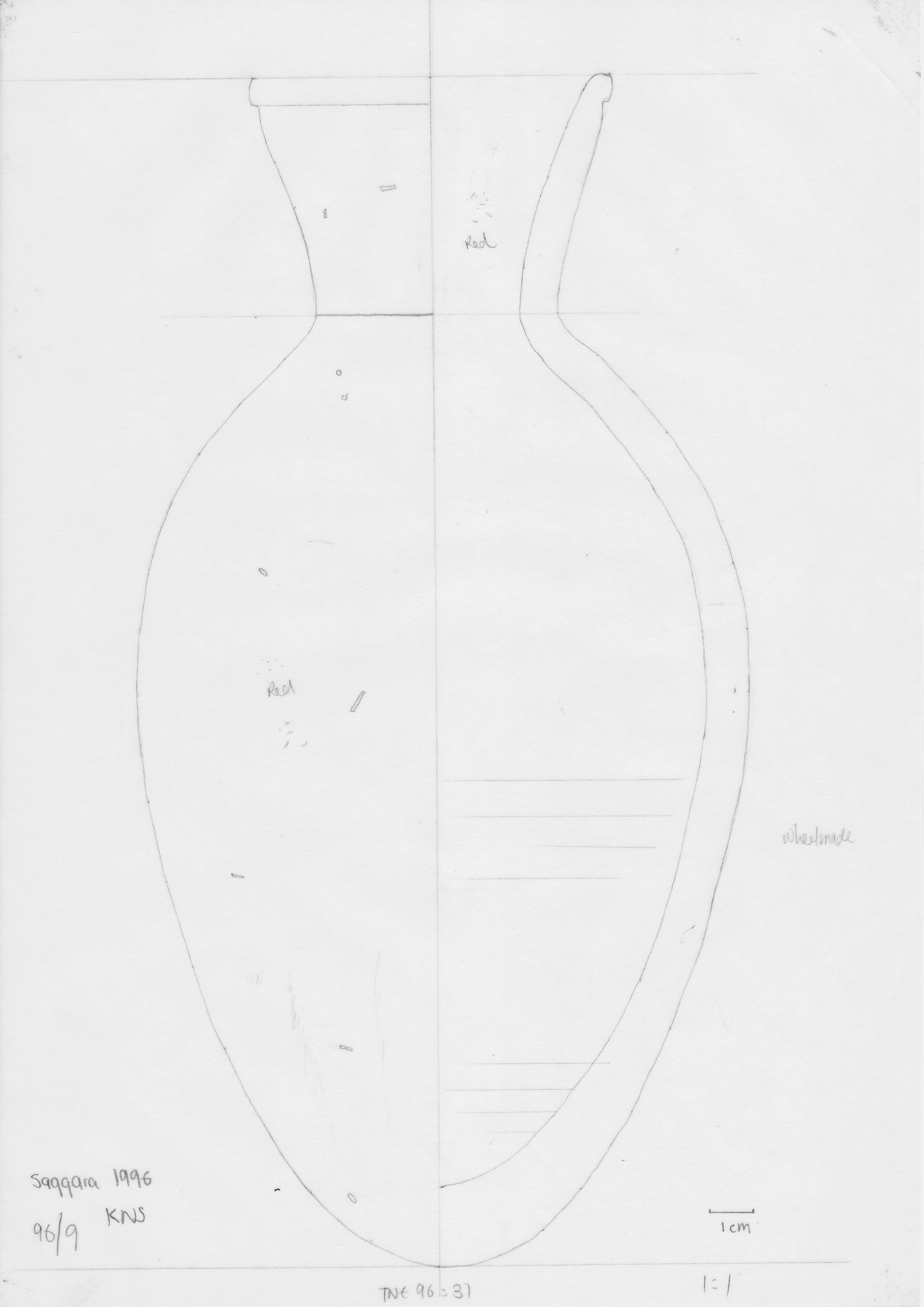
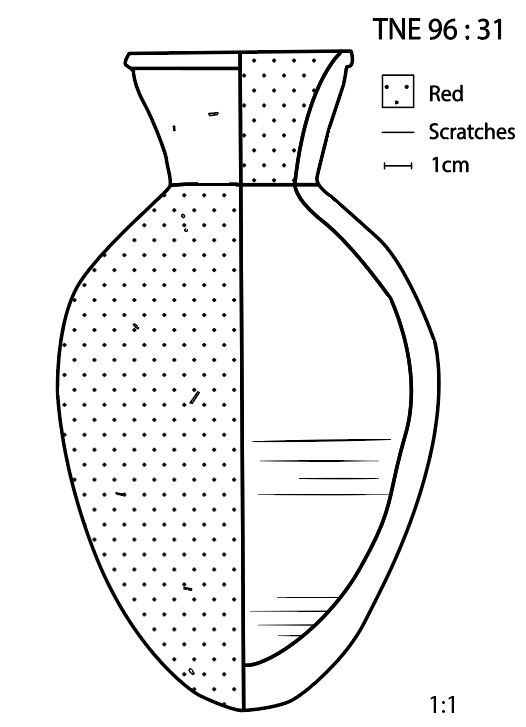
In Semester 2, Week 5 2021, Nathaniel Lowe conducted a tutorial for AHIS3306 regarding how to correctly digitise an artefact illustration for publication. I have not previously worked with Adobe Illustrator before, so this was a new experience for me. Karin Sowada uploaded a folder of illustrations for each person to choose from. I decided to choose artefact TNE 96:31. I chose this one as I thought it would be perfect for a beginner like myself to learn with. There wasn't overly complex detail presented on the wheel-made artefact which for a beginner wasn't as daunting some of the illustrations. As seen below is the original artefact illustration chosen.
Before the tutorial held by Nathaniel, there was an adobe illustrator guide that was required to be read prior to the class. I found the guide to be basic and very detailed for a beginner to follow along with the instructions and tool descriptions. This is my step-by step process of digitising - TNE 96:31.
Step-by-step process...
1. Creating the document
I created the new document and downloaded the original illustration through selecting File > Place. This allowed me to place the image of the illustration on the page and in doing this it created a new layer.
2. Layer 1 - Reference
By creating this new layer, I had to change the name for further referencing. I changed the layer 1 name to 'Reference'. This layer will be the guide I will be following, placed in the background to assist with making this image digitised. Locking this layer prevents any accidental mistakes to be applied to this layer.
3. Layer 2 - Outline
- I created a new layer and named it 'outline', this will be the outline and middle guide of the artefact. Next, I needed to apply the vertical guide onto layer 2. By selecting the pen tool in the left sidebar, I created an anchor point at the top center of the reference, while holding down alt I clicked an anchor point in the bottom center of the reference. This caused a straight line to become created. I ended the line by pressing esc. By clicking on the selection tool and clicking on the newly made line in the 'Appearance' panel there is stroke colour, stroke size and fill. I wanted the stroke colour to be red and the width to be 3pts. While the line is selected I vertically aligned it to the center of the page. Once aligned, I locked the outline layer and unlocked the reference layer. With the selection tool I selected the reference image and aligned the vertical guide with the red line created.
- Once again, lock the reference layer to ensure it wont be changed and now it is time to complete the outline by selecting the outline layer for the next step.
- Tracing the outline of the reference is next. By selecting the pen tool and making sure the stroke colour is red and the width is 3pts, I began to trace. Starting at the top of the vase with a straight line and then following around the body. When a curve was presented I used a bezier curve by holding down the left click and creating the straight line into a curve and angled successfully. Aligning the curve with the reference took some time to get it right, as sometimes I would accidentally un-click and it would lock the curve in at that angle. This required me to undo the curve created and try again. Once completed I double checked that all the lines intercepted with each other. This was required for the following steps.
- Next I selected the shape builder tool in the left sidebar. Once selecting, the shape builder tool options popped up. Within the options, Nathaniel in the tutorial explained to make sure 'Gap Detection', 'Fill' and 'Highlight stroke when editable', were all checked. This will enabled myself to follow along with his instruction and make it easier to use the tool required.
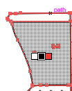
- Now it is time to convert each section into shapes. By pressing command + A, all items are selected. Clicking on the shape building tool and then hovering over a section will provide a grey pattern as seen below. Clicking inside this highlighted area will automatically convert the section into a shape. This was required to be done to all sections of the image.
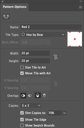
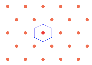
- As seen on the reference image, the exterior and interior of the image are 'Red'. To display this I will be using a stippling pattern. In order to make the pattern I have to initially create a sample circle. This was done by using the ellipse tool from the left sidebar. By clicking and dragging I created the size of the required circle. I noticed you don't want large circles as it affects the pattern's emphasis. Once the circle is created, I made sure the fill is on red and the stroke colour is on none in the appearance panel to the right. Creating the dot pattern, I went to the top option bar and selected object > pattern > make. Choosing the specific settings for my pattern was the next step. Options I chose: the tile type - hex by row, width - 20pts and height 20pts, shown in the image below. To finalise the pattern options I selected 'done' and the pattern uploaded directly into my swatches panel on the right of the page.
- Now the pattern is completed, it is time to fill the areas indicated on the reference image that are red. Using the selection tool, I selected the lower left body shape and in the appearance panel under 'Fill' the pattern is presented. Clicking on the pattern will automatically apply the pattern to the chosen shape. I repeat this step with the upper right shape indicating it is also red. The pattern has now been successfully created and applied.
3. Layer 3 - Detail
- This layer I made specifically for the fine details shown on the reference image.
- As seen on the reference image there are small marks indicating inclusions throughout the clay of organic or non-organic particles. By making the outline layer invisible I clicked on the visibility setting next to the outline layer. I made sure the outline and reference layer are locked to ensure no unwanted changes occur. For these finer details to be created, I selected the pen tool. I zoomed in on the image, as I found it made to the finer details easier to trace over. These details are minimal size so in order to display depth I changed the stroke width to either 0.5 or 0.25.
- The scratches indicate this vessel is a wheel made vessel. Tracing over the lines with the pen tool at the width 1pts. Although the blunt line was to harsh for these marks. By using the width tool in the left hand panel, I was able to readjust the width of the ends of these markings. This changed the abrupt ends to taper off looking more naturalised.
- I reinstated visibility to the outline layer and locked the detail layer.
4. Creating the legend
- With the outline layer selected, I unlocked the layer for adjustments and locked the ones that were not being used.
- Using the type tool I created individual textboxes for the title of the reference, colour indication of the pattern, scratches from wheel marks and sizing. I chose the rectangle tool from the panel on the left and sized it 1:1, placing it next to the textbox saying 'red'. With the selection tool I clicked onto the rectangle created and in the appearance panel, clicking into fill I chose the pattern that was used on the artefact. This automatically filled the box with the same pattern. Next to the textbox stating 'scratches', I drew a horizontal line with the pen tool. This line was same length as the rectangle box. This is situated underneath the description 'red'. Finally, in regards to '1cm', I copied the line drawn for 'scratches' and placed it next to '1cm'. With the line selected that is placed next to '1cm', I decided to apply arrowheads to either end. This was accomplished by clicking onto the word 'stroke' in the appearance panel, while the line is selected. Further options opened, scrolling down to arrowheads and I chose 'arrow 27' for both ends. This provided the end of the line with a short vertical end as shown in the finalised product. Selecting all the legend items, next I go in the options panel at the top of the program. Select object > group. This grouped all items together and made it easy to move to the desired position without needing to do it individually.
5. Trim Guidelines and Group
- It was quite easy to accomplish this step among the outline layer. When I converted each section into shapes earlier this disconnected the over hanging line from the shapes created. With the selection tool chosen, I clicked onto the over hanging line and it disconnected easily from the artefact drawing. Once disconnected it can be deleted. I completed this step for the overhanging line on the top and the bottom of the artefact.
- Lastly, I selected everything by clicking command + A and in the upper options panel click object > group. This will group all the elements together.
6. Recolouring the Image
- To recolour the image, I clicked command + A, this will select everything. With the selection tool chosen, I clicked on the colour wheel window in the upper panel. Once the window opened I chose 'Advanced settings', and changed the B to 0%. This automatically changed the entire image black.
7. Expanding the Image
- The next step I expanded the image causing the paths to turn into shapes. After saving a copy of my work I selected everything with command + A. Turning to the top options panel clicking on object > expand. I made sure the object, fill and stroke were checked and finished by clicking 'OK'. This step actually had to be repeated a few times as I had some trouble and some areas of the image weren't expanding. Eventually the entire image was expanded.
8. Exporting the Image
Finally, the last step is to export the image. By clicking into the top options panel file > export > export as. I renamed the file, and chose the format SVG for the image to be exported as. An options screen for SVG popped up and I left it as default. The below image is the finalised product of the artefact illustration.
